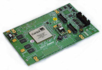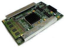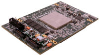
coretile express 板在 versatile™ express 开发系统中提供主系统 cpu。coretile 必须与提供电源、配置和外设连接的主板 express uatx 板配对使用。
处理器子板 express 板与 versatile 产品系列中的前代产品的不同之处在于,其内存和 lcd 控制器等高带宽外设是与 arm 处理器一起在测试芯片中实现的。这会显示提升性能,使系统更适合进行软件基准测试并完全能运行 debian linux 等桌面操作系统。
处理器子板 express 系列支持的 arm 处理器有:
- cortex™-a15 mpcore
- cortex-a9 mpcore
- cortex-a7 mpcore
- cortex-a5 mpcore
| 处理器子板名称 |
coretile express |
coretile express 适用于 cortex-a9 |
coretile express 适用于 cortex-a5 |

|
|

|
|
| 处理器子板名称(简称) | v2p-ca15x2_ca7x3 | v2p-ca9x4 | v2p-ca5x2s |
| 部件号 | v2p-ca15-0314a | v2p-ca9-0301a | v2p-ca5-0305a |
| pcb 号 | hbi-0249 | hbi-0191 | hbi-0225 |
| 数据表 | 数据表 | 数据表 | 数据表 |
| 手册 | 用户手册 | 用户手册 | 用户手册 |
| 产品视频 | n/a | n/a | 视频 |
| cpu 类型 |
cortex-a15 mpcore™ |
cortex-a9 mpcore | cortex-a5 mpcore |
| cortex-a7 mpcore™ | |||
| cpu 数量,速度 |
双核 ca15,1ghz 三核 ca7,800mhz |
四核,400mhz | 双核,100mhz |
| cpu 版本 | r2p1,r0p1 | r0p1 | r0p1-rc0 |
| 协处理器 | neon™ | neon | neon |
| l1 高速缓存 i/d | 32kb/32kb | 32kb/32kb | 32kb/32kb |
| l2 高速缓存 | 1mb | 512kb | 256kb |
| tcm | n/a | n/a | n/a |
| sram(片上) | 64kb,64 位 | 16kb,64 位 | 64kb |
| sdram | 2gb ddr2,32 位 | 1gb ddr2,32 位 | 1gb ddr2 sodimm |
| sdram 速度 | 400mhz | 266mhz | 120mhz |
| amba 总线类型 | axi | axi | axi |
| 内部 amba 总线速度 | 500mhz | 200mhz | 100mhz |
| 外部 amba 总线速度 | 50mhz (m) | 50mhz (m)、30mhz (s) | 40mhz (m)、40mhz (s) |
| 嵌入式跟踪 | 16/32 位,ptm,etb (4kb) | 16/32位,ptm,etb (8kb) | itm,etb (8kb) |
| 调试连接 | jtag 和 swd,20 针 dil | jtag 和 swd,20 针 dil | jtag 和 swd,20 针 dil |
contents
coretile express a15×2 a7×3 technical reference
manual
preface
about this book .......................................................................................................... vii
feedback .................................................................................................................... xi
chapter 1 introduction
1.1 about the coretile express a15×2 a7×3 daughterboard ....................................... 1-2
1.2 precautions .............................................................................................................. 1-4
chapter 2 hardware description
2.1 coretile express a15×2 a7×3 daughterboard architecture .................................... 2-2
2.2 cortex-a15_a7 mpcore test chip ............................................................................ 2-4
2.3 system interconnect signals .................................................................................... 2-6
2.4 power-up configuration and resets ........................................................................ 2-10
2.5 serial configuration controller (scc) .................................................................... 2-21
2.6 voltage control and process monitors ................................................................... 2-22
2.7 clocks .................................................................................................................... 2-24
2.8 interrupts ................................................................................................................ 2-34
2.9 hdlcd .................................................................................................................. 2-38
2.10 ddr2 memory interface ........................................................................................ 2-39
2.11 debug .................................................................................................................... 2-40
chapter 3 programmers model
3.1 about this programmers model ................................................................................ 3-2
3.2 daughterboard memory map ................................................................................... 3-3
3.3 test chip scc registers ......................................................................................... 3-12
3.4 programmable peripherals and interfaces ............................................................. 3-54
appendix a signal descriptions
a.1 daughterboard connectors ...................................................................................... a-2
a.2 hdrx hsb multiplexing scheme ............................................................................. a-3
a.3 header connectors .................................................................................................. a-5
a.4 debug and trace connectors .................................................................................... a-6
appendix b hdlcd controller
b.1 introduction .............................................................................................................. b-2
b.2 hdlcd programmers model ................................................................................... b-3
appendix c electrical specifications
c.1 ac characteristics .................................................................................................... c-2
appendix d revisions


 关于米尔
关于米尔 js555888金沙老品牌的产品中心
 定制服务
定制服务 服务中心
服务中心 联系js555888金沙老品牌